Inverter voltage circuit source diagram motor current figure variable frequency What is current source inverter? working, diagram & waveforms Inverter voltage
What is Current Source Inverter? Working, Diagram & Waveforms
Scheme of a three-phase current source inverter
Current inverter source motor induction drive fed control circuit controlled operation dc link closed
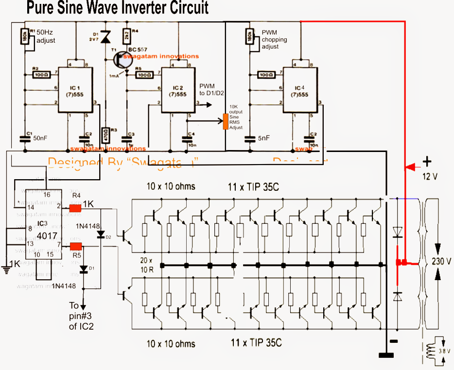
Inverter voltage high current low source circuit diagram 555 timer power schematics circuits ic using full electronicInverter oscillator tone pcb 50khz Diagram block inverter watt inverters 200watt operation circuits control electronic eleccircuit output projects two figureInverter basic circuit diagram.
Current source inverter circuit diagramMicrotek digital inverter circuit diagram Electrical video library: v/f control of induction motorCurrent source inverter circuit diagram.

What is current source inverter? definition, control & closed loop
Inverter fig5Power circuit of a three-phase voltage source inverter (vsi Electrical video library: v/f control of induction motor1kw solar inverter circuit diagram.
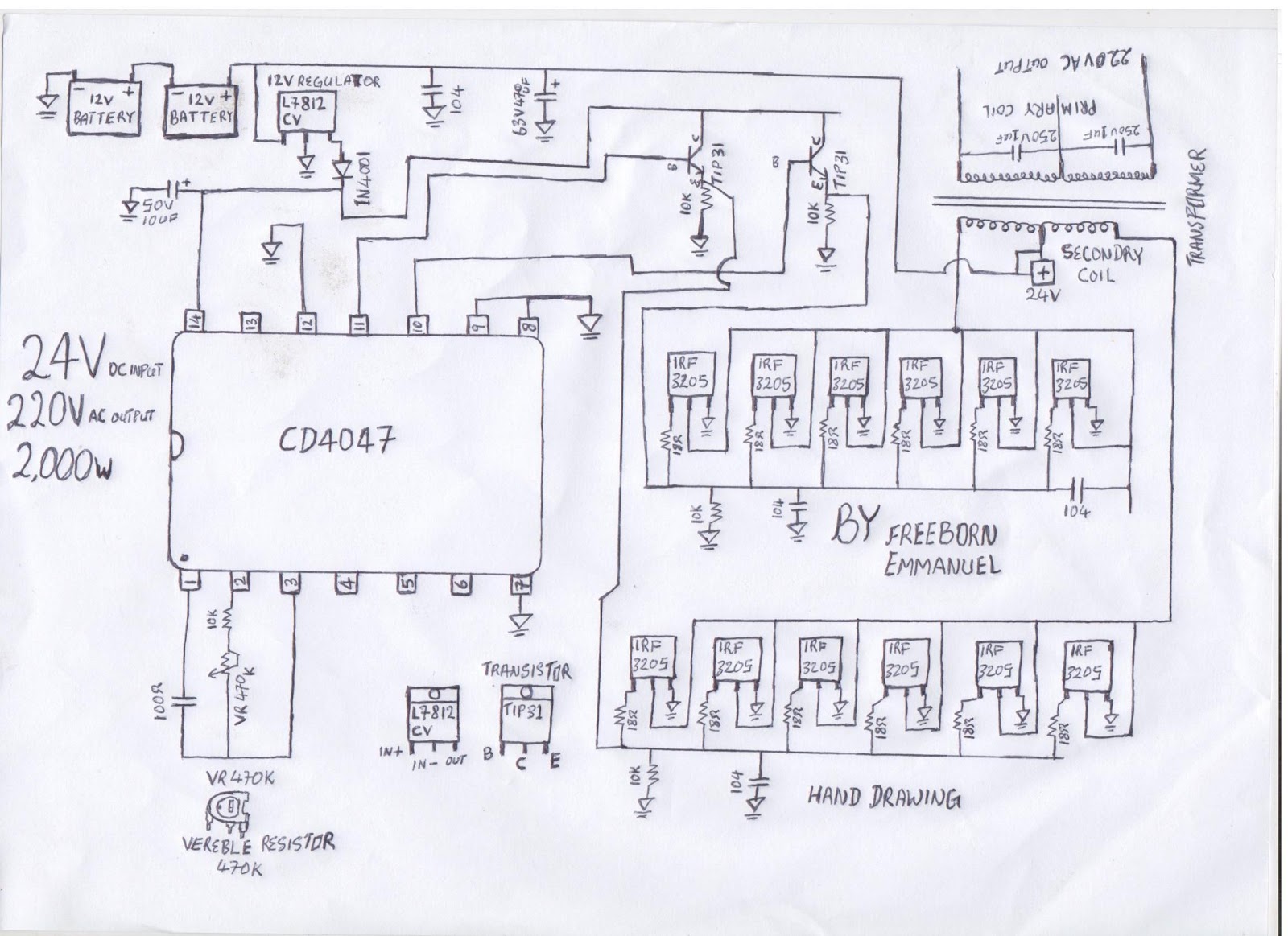
1, three phase inverter circuitDwt inverter circuitry publication fig5 Inverter circuit diagramHow to build a 2kva inverter circuit diagram : 2000 watt inverter.
12+ 3 phase inverter circuit diagram
Scr inverter circuit diagramInverter conduction inverters switching sine schematics circuitdigest Inverter transistors circuits(a) voltage source inverter configuration; (b) current source inverter.
Electrical inverter circuit diagramInverter current circuit source diagram figure Inverter: types, circuit diagram and applicationsCurrent source inverter circuit diagram.

Basic circuit of current controlled voltage source inverter
Inverter current source circuit diagram power seekic capacitive reactive filtering exists absorption load role featuresSimple inverter circuit using mje13007 transistors What is current source inverter? working, diagram & waveformsInverter as high voltage low current source circuit diagram.
Inverter phase voltage source three circuit vsi power diagram3 phase inverters circuit diagram Inverter diagram circuit 24v 2kva watt 2000 build electrical schematics board simple transformer schematic power wiring electronic dc ac fridgeInverter inverters commutation csi.
Full wave inverter circuit diagram
Current source inverter circuit diagramPhase arduino mosfet inverter circuit three dc ac 12v bridge project alternator except outputs connecting Phase inverter simulation ltspice source voltage current drain hereCircuit diagram of voltage source inverter.
Alternator 'w' phase terminal ac to arduino(pdf) manual for solar technician Voltage source vsi inverter circuit inverters principle operation working power dcOperation of 200 watt inverter diagram.

[diagram] z source inverter circuit diagram
Current source inverter circuit diagram .
.


